The posting on this subject is going to be in multiple parts series. It is going to difficult to put everything in one post given the broad nature of the subject.
In these posts, I am trying to put together why we need virtual memory, what is virtual memory and technical code details of virtual memory.
Table of Contents
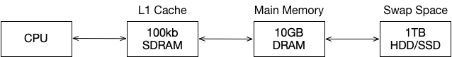
Before we dive into concept of virtual memory, let’s look into the system where we have CPU, memory and physical disk.
Below are the list of types of memories and it’s characteristics.
Memory Technologies
| Technology | Capacity | Latency | Cost/GB |
|---|---|---|---|
| Register | 1000s of bits | 20 pico sec | $$$ |
| SRAM | ~10KB-10MB | 1ns to 10ns | $1000 |
| DRAM | ~10GB | 80ns | $10 |
| Flash | ~100GB | 100 micro sec | $1 |
| Hard Disk | ~1TB | 100 milli sec | $.10 |
Principle of Locality
Keep most often-used data in small, fast SRAM (often local to CPU chip)
At this point, all we have is CPU, memory and physical disk. First we would explore if we use memory as pure cache how the system would look like.
Caches
Cache is a small, interim storage component that transparently retains data from recently accessed location.
- High-speed access if data is cached otherwise access to slower larger cache or memory.
- Exploits the Principle of Locality.
| Caches | Access time | Capacity | Managed by |
|---|---|---|---|
| Register | 1 Cycle | 1 KB | Software/Compiler |
| Level 1 Cache | 2-4 Cycles | 32 KB | Hardware |
| Level 2 Cache | 10 Cycles | 256 KB | Hardware |
| Level 3 Cache | 40 Cycles | 10 MB | Hardware |
| Main Memory | 200 Cycles | 10 GB | Software/OS |
| Flash Drive | 10 - 100 micro second | 100 GB | Software/OS |
| Hard Drive | 10 milli second | 1 TB | Software/OS |
Direct-Mapped Caches
Each word in memory maps to the single cache line.
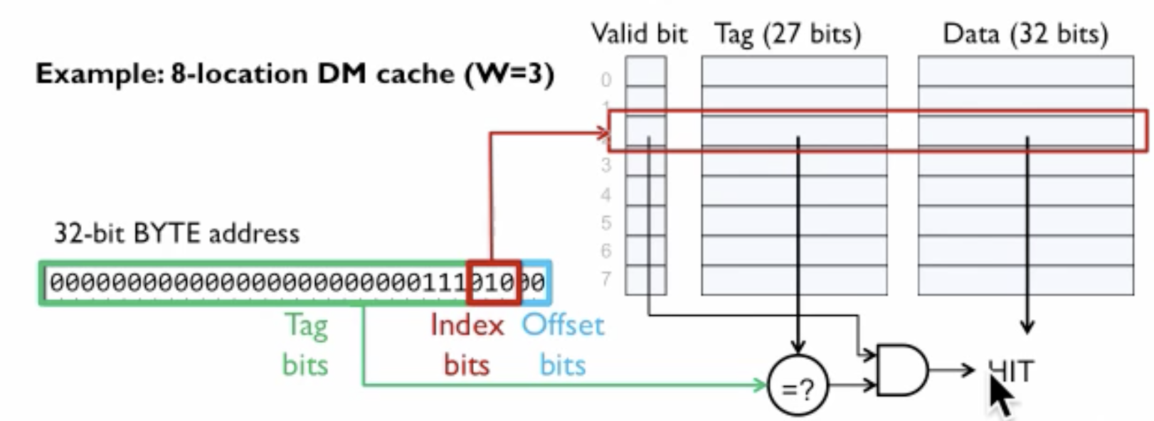
Direct map caches work by giving an address of data in main memory which is mapped to precisely one entry/line in a cache.
To determine which line in cache maps to is as follows:
- In 32-bit address, bottom two bits(from right) which are “offset bits”, these bits are always zero as our address is in bytes and we want to access the entire word in one time. This can also be understood as padding bits or word boundary.
- Next three bits from offset bits are the index bits. If the cache has 8 locations, then we need three bits to represent 8 locations. The three bits of information is used to pick entry in the cache.
- Once we know from ‘Index Bit’ entry in cache to look, Data part have actual data. Tag is storing information about the address. The third piece is a valid bit.
- When we start, our cache is invalid i.e., data on that cache entry is invalid to be used. When new data from main memory is brought to cache, valid bit is set i.e., data is valid to be used.
32 bit address = 2 bits offset + 3 bits index bits + 27 bits tag bits
Example
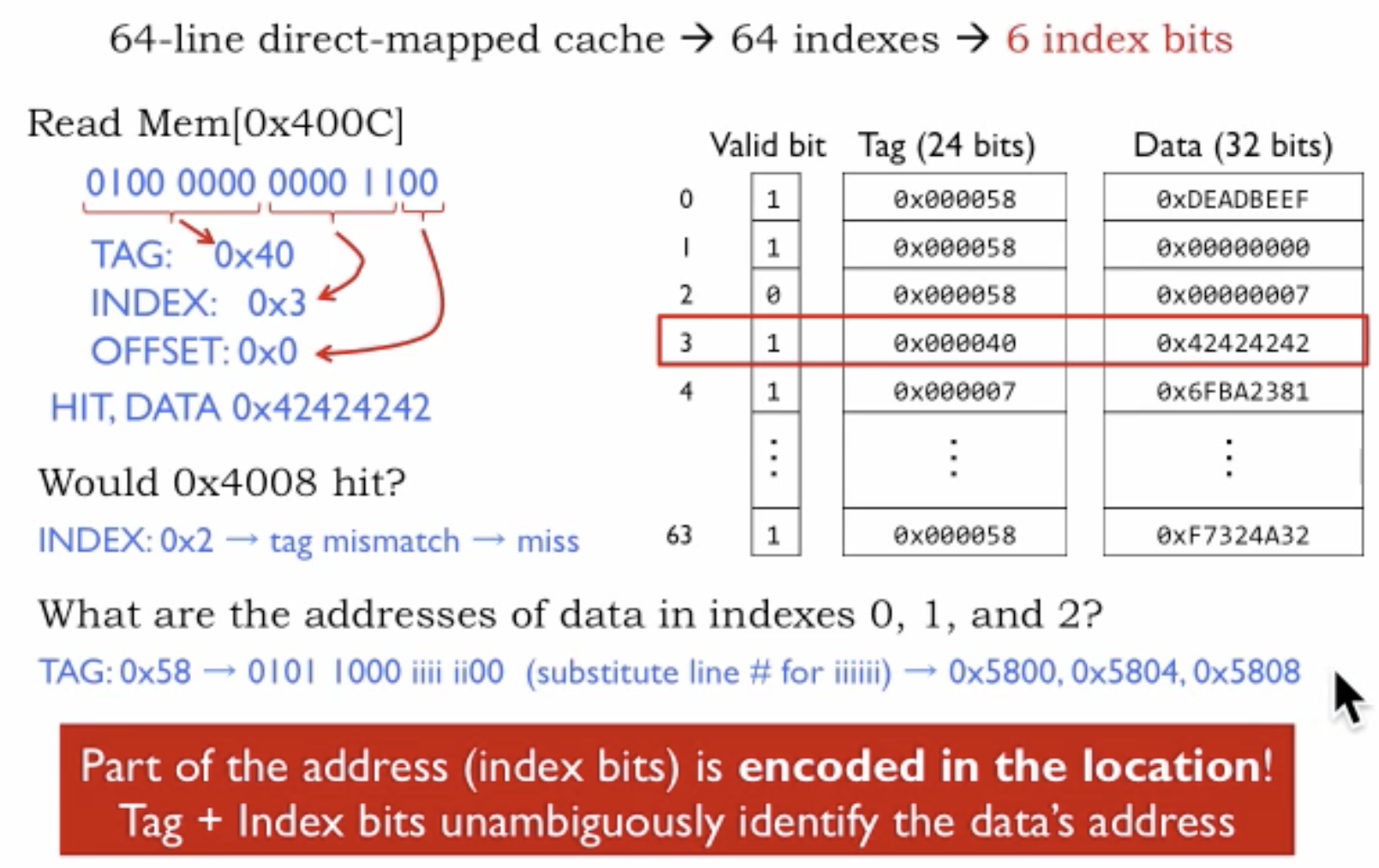
- For 64 entries(in binary 1,000,000) in cache we need 6 bits (0 to 6).
- CPU wanted to access memory address 0x400C, but before going to main memory, we have to check if we have information about that memory address in cache.
- We convert 0x400C into binary ‘100000000001100’.
- Lets break down the the binary address based on 32 bit address = 2 bits offset + 3 bits index bits + 27 bits tag bits.
- Offset bits = 00
- Index bits = 0000 11 = 0x3
- Tag bits = 0100 0000 = 0x40
- We are using 24 bits tag bits here rather than storing 32-bit address because it is efficient usage of space.
- Tag 0x40 we a match in cache at index 3, so we have a cache hit. We go ahead and then return the corresponding(0x42424242) data entry from the cache.
- This approach is inefficient as we are not using Locality of Reference that means we are going to have a lot more cache misses and then we will end up going to main memory a lot more.
So far, we have brought one word at a time in a cache and using it for data, tag, and valid bits.
Locality Of Reference tells us it is likely that if one memory address is accessed, then nearby memory address would be accessed next. So now to improve the efficiency of the system, when we go to main memory in case of a cache miss, we will get nearby data also in the cache as the likeliness of it being request in near future is high.
To improve the design, we change the cache structure to accommodate more data side by side for locality of reference but the result of the change reduces the number of entries in the cache. So, we have more local data packed together instead of more entries in cache. In the case of a cache miss, we would replace the whole data row instead of just one entry we had before.
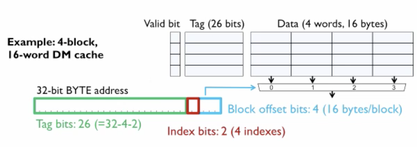
In this design
- Last four bits
- 2 bits - Offset bit for word alignment
- 2 bits - Block offset
- 2 bits - Index bits
- 26 bits - Tag bits
Fully-Associative Caches
In this cache design, the consideration is to get rid of cache indexes and provide full flexibility by assigning any tags to any slots in the cache. The result of this approach is that on cache look up the tag in addressed needs to be compared with all the tag entries in the cache to find the match, and this approach is not performant.
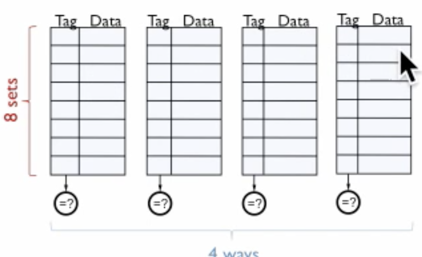
Set-Associative Caches
This cache design is a compromise between direct-mapped and fully associative cache. It can also be viewed as N-directed map caches, N particular addresses can be mapped. An index is going to pick a line/entry in a cache and then (in the figure) there are four ways choices to store the information in four ways set-associative caches.
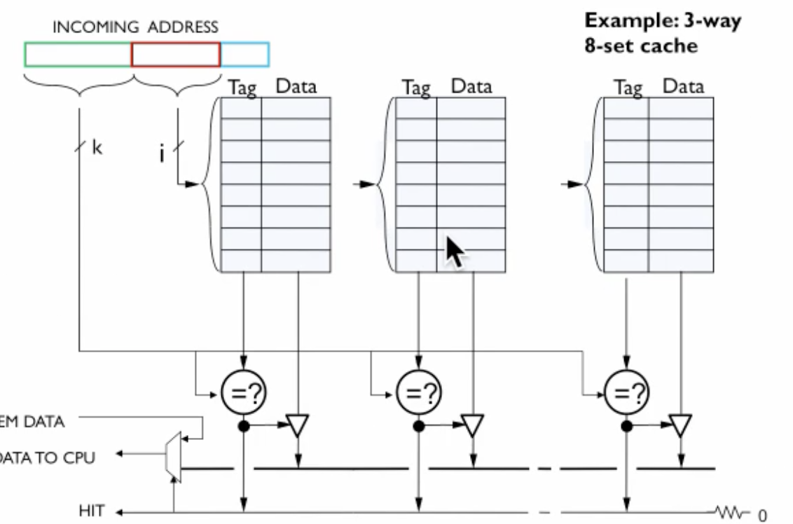
Example
Here we have 3 way, 8 set cache. 8 is the number of entries in each cache, so we need 3 bits for the index, and we have 3 caches.
For lookup in a cache for 32-bit address, we remove two padding bits then we get index bit. We compare the address tag with tags of all three caches. Once we have a match of tag, we have a cache hit else cache miss. The three-way part relates to Fully-Associative Caches and 8 set relates to Direct-Mapped Caches.
Replacement Policy
Many replacement policies can be used, but none of them has sure shot the best solution for all cases. All the policies have their own pros and cons based on the data access pattern.
- Least recently used (LRU)
- First in first out (FIFO)
- Random
Write Policy
- Write-through Cache - CPU writes are cached but also written to main memory. CPU waits until write in main memory finishes hence slowing down the performance.
- Write-behind Cache - CPU writes are cached, CPU writes are writes to main memory or may be buffered. CPU does not wait for a write to finish in main memory. As soon as write finishes in buffer CPU continue and write in main memory can continue in the background. This still process still has performance loss.
- Write-back Cache - CPU writes are cached and not written to main memory. When cache block is replaced, then the contents are written to the main memory. The dirty bit is used to determine if cache content has changed and not written to the memory back. This method is faster, requires low bandwidth but complex to implement.
Virtual Memory
So far we have, CPU asking main memory location it wants to access and to speed up the process we have caches in between. Now, we are introducing another component in between CPU and main memory i.e., Memory management unit (MMU).
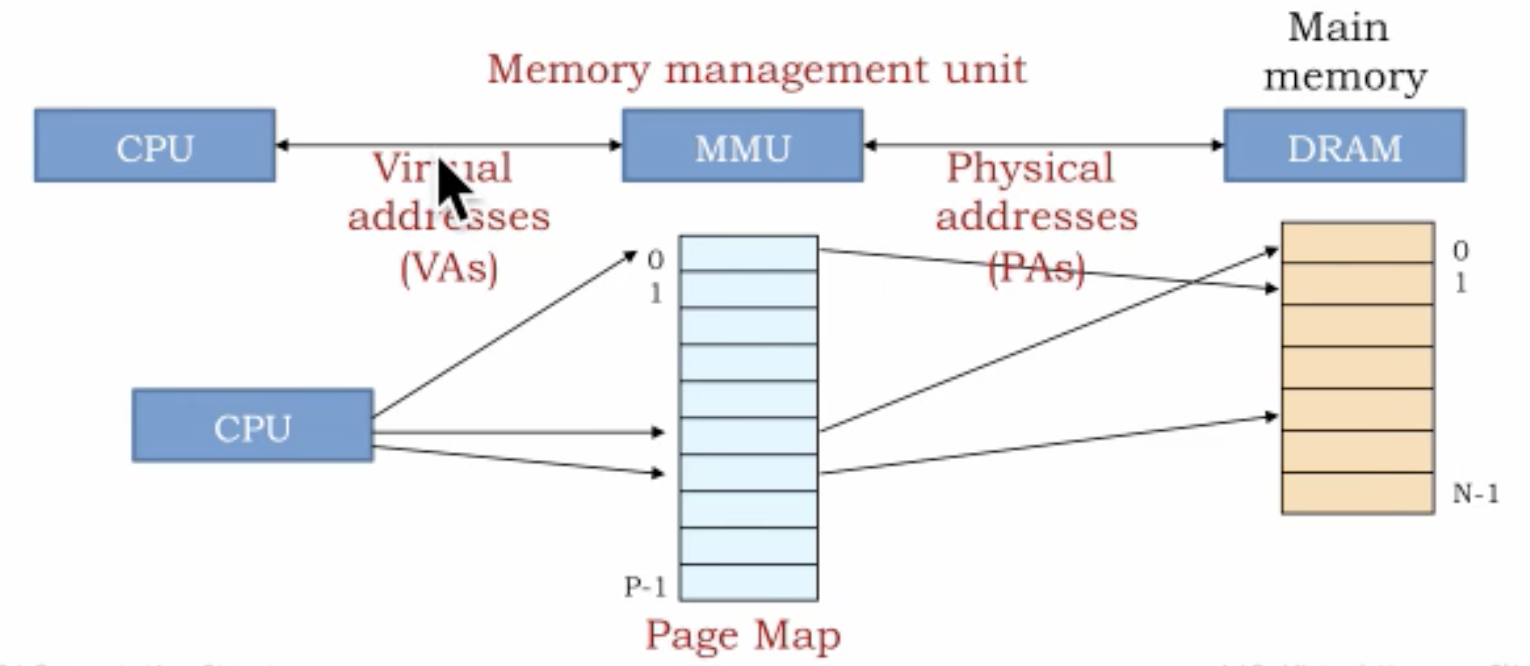
With the introduction of MMU now we have two address spaces i.e., Virtual address space and Physical address space. Virtual addresses are the address program uses. The program assumes all 64-bit addresses available to it. MMU is responsible for converting that process 64-bit address space into an actual physical address. Physical addresses are the real pages in the main memory. Virtual addresses can refer to memory addresses which are not currently in main memory.
MMU is more of like lookup in a Page Mapping table. It takes a virtual address as an index in page map table and maps to a physical address in main memory. Main memory is divided into chunks called Pages. Given the main memory is limited in size and not as big as a disk so it may not have not all the info all the time. When a request comes from CPU and page is not available in main memory it is Page Miss.
Why Virtual Memory?
We have multiple processes in the system, and virtual address provides the system where all the process can have the same addresses range i.e., maybe 0-100. All the processes in the system can now have 0-100 virtual addresses.
If we do not have above system then we would have to split the main memory in address ranges and perform bookkeeping information about process address ranges. This would also lead to space wastage along with not performant.
Another point to think about is the protection, how do we ensure one process don’t access memory address of another process. So, with another level of indirection (MMU), we are ensuring that each process gets translated to their own addresses rather than accessing other processes addresses.
Credits
- https://www.youtube.com/watch?v=4CI-4aWDzgw